Washing Assistant
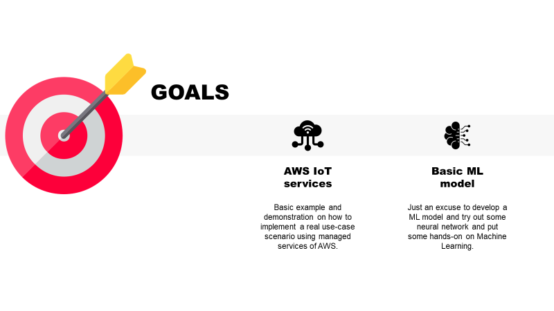
The project originated while working as a Consultant using AWS. Its main objectives were:
- Implement and end-to-end IoT project using AWS managed services in order to put in practice what learnt preparing AWS Solutions Architect Associate (SAA) exam;
- Have an excuse the try out some neural network applied to a pseudo-real problem.
The main ideas of the project are:
- To implement a connected washing machine appliance, able to receive and execute remote control from the Cloud (AWS);
- To be able to choose a washing program automatically just by sending some picture of what needs to be washed.
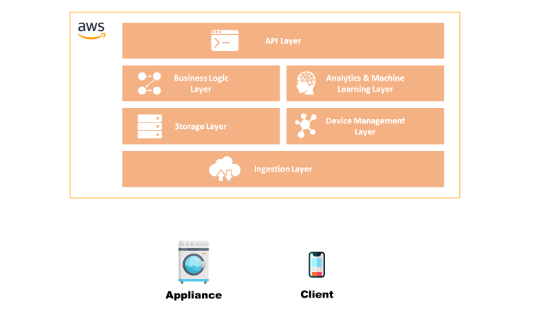
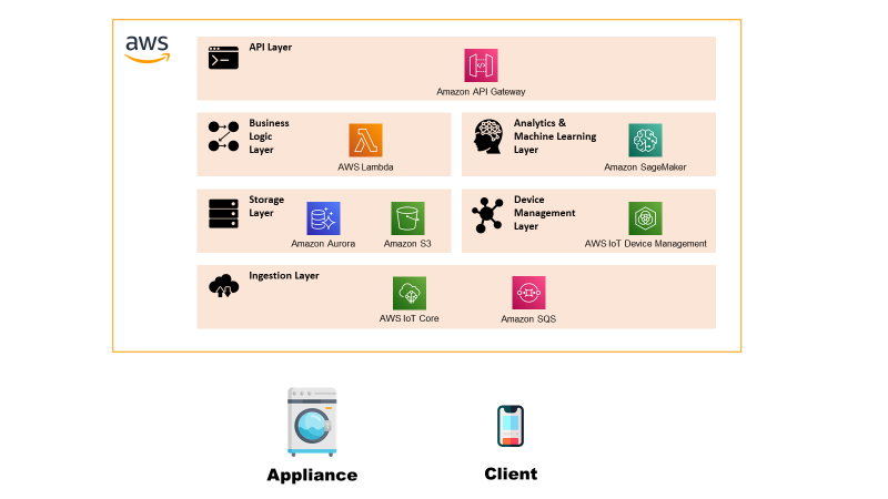
In this section is defined at a high-level the blocks that compose the solution in order to get an understanding of the system:
- Appliance: the block acts at the Thing of the system, able to receive and execute commands and send basic telemetry.
- Client: this is the control pane from where a user can see the status of the appliance or send a new command.
- IoT Platform: the platform serves the main purpose of any IoT platform, such as communicate securely with the Things, implement remote control and managing the devices. It is composed by: Ingestion Layer: layer that establishes a secure connection with the things and ingests the telemetry data.
- Storage Layer: layer that stores the received data as history.
- Device Management Layer: layer that allows to manage the device, such as updating the firmware.
- Business Logic Layer: layer that implements the business logic of the process.
- Analytics & Machine Learning Layer: layer that executes intelligent algorithms.
- API Layer: layer that exposes APIs for interacting with the platform from a client.
In this section there is the description of the Low-Level Architecture of the solution, i.e. explanation of what it’s inside each functional block.
Appliance
The appliance represents the “Thing” of the system and is implemented with two functionalities: control panel from where it’s possible to see the current washing machine status and a log console in order to show what the machine is doing. The component is implemented as an emulator developed in Python.
Client
The client in this case is represented as a Web-App/Mobile App from where it’s possible to send new commands to the appliance passing from the platform.
Ingestion Layer
The ingestion layer has the main task of verifying device identity guaranteeing the security of the solution, routing telemetry messages within the platform and sending to Things received commands.
The chosen services for this layer are:
Storage Layer
The layer has the task of storing the data required for the application to work. The types of data are telemetry/commands data which are exchanged between the platform and the Things and the data related to the two static Web-Apps hosted on the platform.
The chosen services for this layer are:
Device Management Layer
The device management layer allows an admin of the system to execute a remote firmware update of the appliance.
The chosen services for this layer are:
Business Logic Layer
The business logic layer contains all the compute services that are required to “customise” the IoT processes, like the telemetry, remote control and firmware update.
The chosen services for this layer are:
Analytics & Machine Learning Layer
Layer that hosts the Machine Learning models used for implementing the Washing Assistant.
The chosen services for this layer are:
API Layer
Layer that exposes securely REST endpoints for allowing a user to interact with the platform.
The chosen services for this layer are:
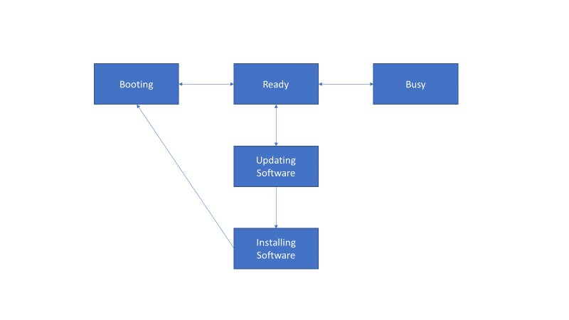
The emulator has the task to simulate the presence and behaviour of the Washing Machine. To do this, a simple State Machine was implemented in order to model the behaviour. The emulator was developed in Python using boto3 and AWS IoT Core libraries and TkInter for the UI.
The state of the state machine are:
Here below a graphical representation of what are the transitions from one state to the other.
Before starting with a description of the flows, it’s worth describing the Machine Learning model as it consists of different algorithms that have different requirements in terms of compute and resources.
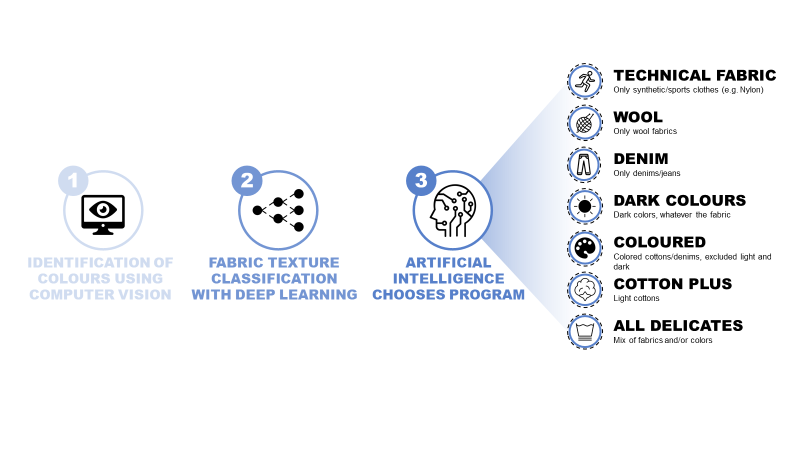
Colour Identification
The first step is analysing the image in order to identify the major colours present in the fabric. The algorithms uses OpenCV and ScikitLearn for clustering pixel-wise the image into a set of main colours. For the clustering is done using K-Means.
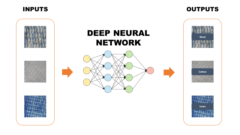
Fabric Classifier
This part was the most complicated and time consuming.
The tools used for training and evaluating neural networks was CoLab with Jupyter notebooks. The framework used was Tensorflow.
The original dataset used consists of some thousand pictures labelled in 7 fabric categories. It’s quite a difficult task as some fabric are very diverse in the aspect and look similar to one another. Only with very careful eye it’s possible to tell them apart.
The first candidate for this task was GoogLeNet, whose detailed explanation can be found at this link. In addition to some difficulty in the convergence, the main reason why I discarded this option was the poor accuracy, which was not sufficient for the task.
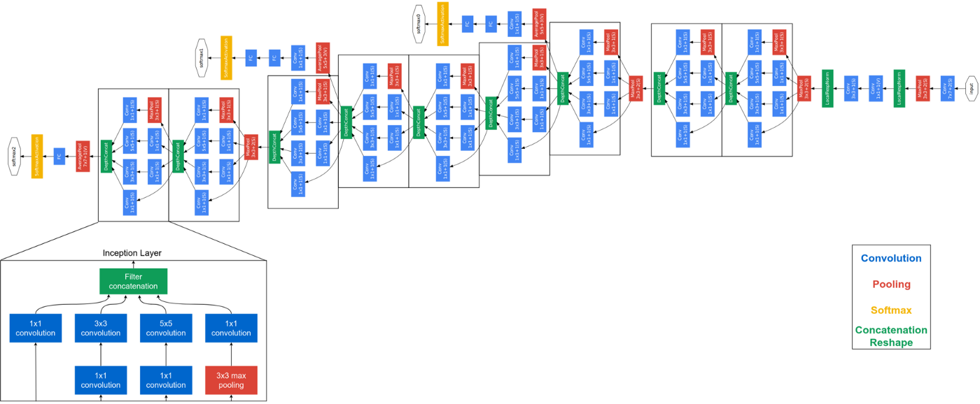
What I learnt from the first experiment was that it was hard to extract features by training a normal deep convolutional neural network. I could see something after a lot of epochs, but as said the results remained always poor.
Therefore, the second and last attempt consisted in the implementation of an auto-encoder in order to force the extraction of efficient features. After training, the auto-encoder was cut at the bottleneck, i.e. taking away the decoder part, and attaching at the end some fully-connected layer as basic classifier.
For more details on auto-encoder refer to this link.
The results of this approach were astonishing and allowed to obtain more than 90% accuracy on predicitions. Here below I report pieces of code that show the network architecture and other minor details (e.g. activation functions).
Encoder
Decoder
Classifier
Program Selector
Once the colours and the fabric of each cloth are identified, it’s time to select the program. To do so, a simple decision tree suffice for selecting the most appropriate program.
This section contains the main architectural flows which serve as example to understand how the platform works.
Remote Control Flow
The flow implements the functionality of remotely sending and executing commands on the appliance.
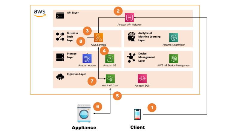
The steps are:
- Client (e.g. Mobile App) sends a request with command details to the API Gateway.
- API Gateway, after verifying authorisation, triggers a AWS Lambda.
- AWS Lambda stores the command request in Amazon Aurora for keeping history.
- AWS Lambda sends a message to the AWS IoT Core.
- AWS IoT Core routes the message to the appliance.
- Appliance executes the command and sends back a message with updated status.
- AWS IoT Core routes this back to a AWS Lambda.
- AWS Lambda updates command record on Amazon Aurora.
Washing Assistant Flow
The flow describes how the Washing Assistant model works and interacts with the system. The remote control part of the flow is simplified for sake of simplicity. See previous section for more info.
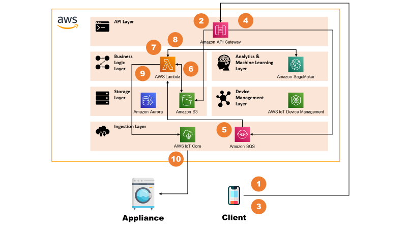
The steps are:
- Client uploads one or more images to the API Gateway using REST.
- API Gateway routes this to S3, which stores the objects.
- Client invokes again the API Gateway with the Washing Assistant request, that contains also the reference to uploaded pictures.
- API Gateway places the requests on an Amazon SQS queue.
- Message on Amazon SQS triggers a AWS Lambda.
- AWS Lambda retrieves the images from S3.
- AWS Lambda processes the images by analysing major colours in each image.
- AWS Lambda invokes Amazon SageMaker for detecting fabric of each image.
- After having taken a decision based on clothing inputs, AWS Lambda sends a message to the AWS IoT Core.
- AWS IoT Core routes the message to the appliance, which executes it.
For sake of optimisation, in reality the call at point 8 is asynchronous and is done in parallel to point 7 so that latency to produce output is lower.
It was also taken into account the possibility to decouple further the “standard” processing (Colours Identification, Program Selection) by putting another SQS queue connected to AWS Lambda and then SageMaker. In this way, in case of multiple images, the system would automatically scale and keep the latency low. This was not implemented as it would have been out of scope for current pilot.
Firmware Update
The flow describes how the system implements a Firmware Update functionality.
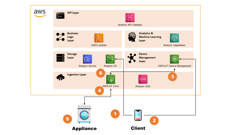
The steps are:
- The system admin uploads a new firmware package on dedicated Amazon S3 bucket.
- System admin triggers the firmware update from the AWS IoT Device Management consolle. From here, it indicates the metadata of the update (e.g. S3 object id, package signature) and the target device population.
- AWS IoT Device Management consolle notifies the AWS IoT Core of the events.
- AWS IoT Core routes the message to the appliance, indicating the metadata of the update.
- Appliance downloads the package, verifies the signature and, if verified, proceeds with the update. It then reports back the correct operation to the AWS IoT Core.
- AWS IoT Core routes the message to the AWS IoT Device Management which shows the update on the consolle.
Additional remarks
For sake of simplicity, device certificates were generated directly from the Root CA. In real case scenario, obviously this would be done by some Intermediate CA but it would have taken useless time for this project.
Moreover, also for Firmware Update the PKI setup was very much simplified by using a single self-signed certificate.
The section contains the outputs of the project, which mainly consist of UI used for interacting with the system.
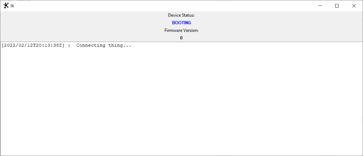
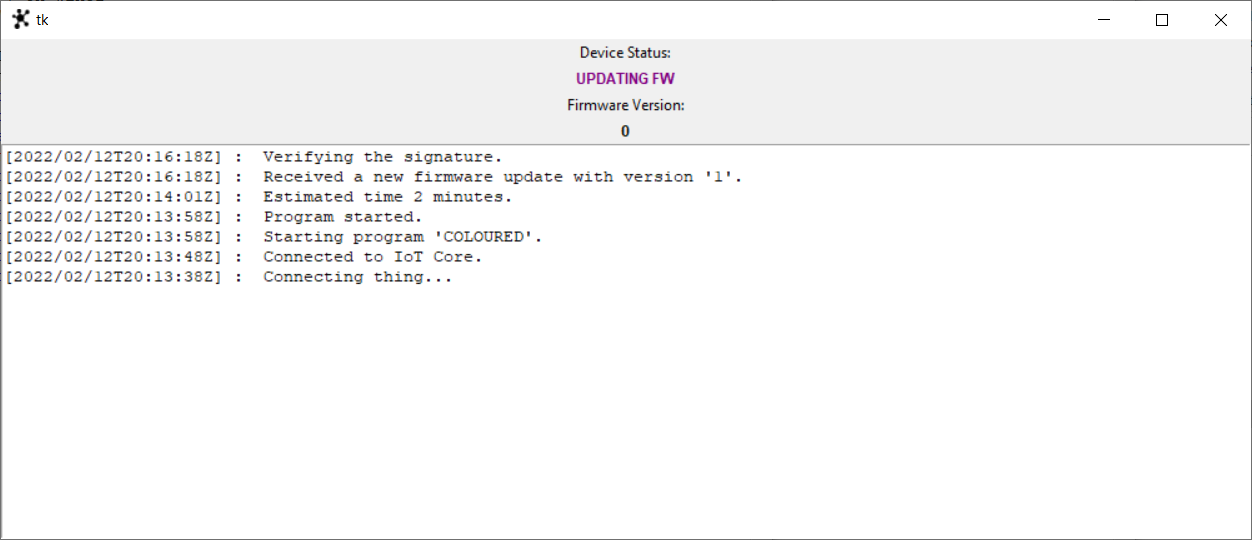
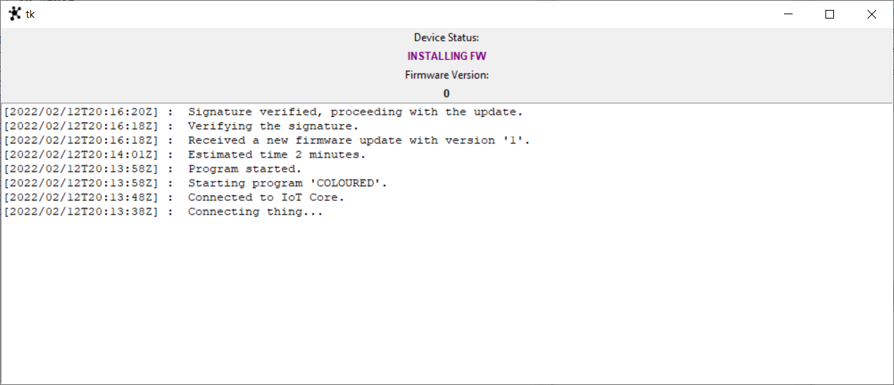
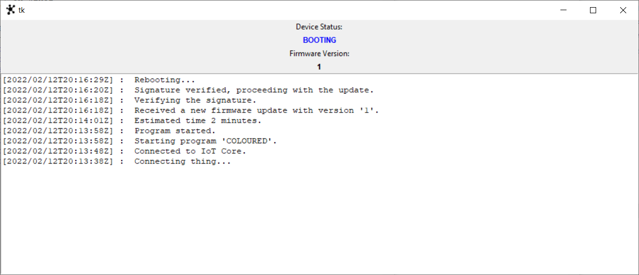
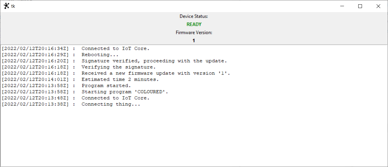
Emulator
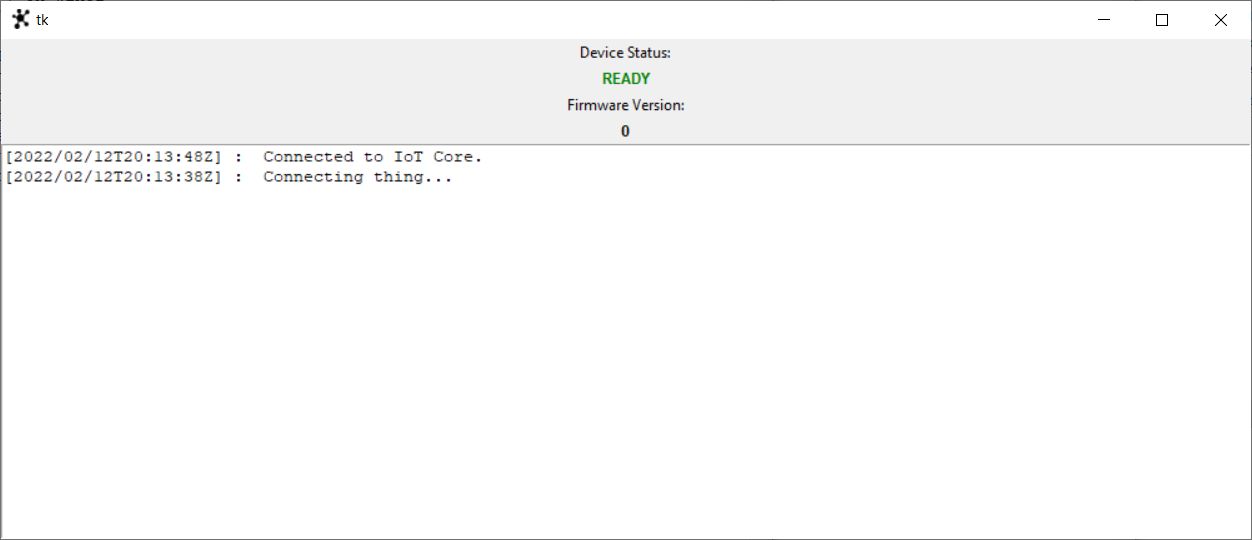
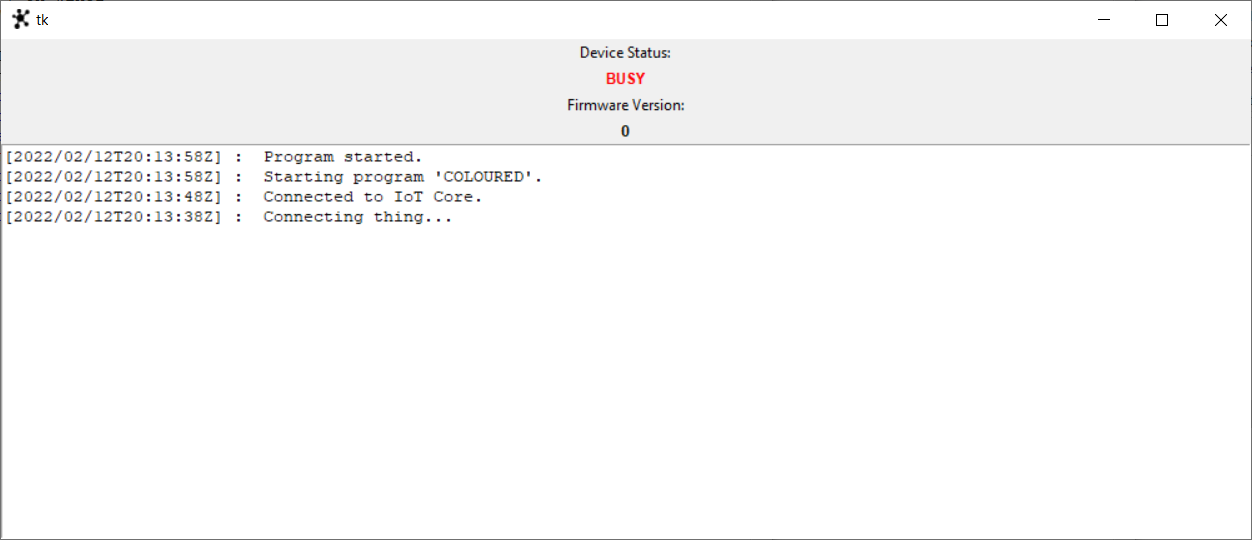
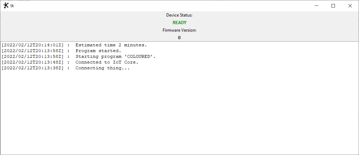
Here below some picture related to the emulator UI and the related states.
The sequence of actions taken are:
- Booting the appliance and waiting for the appliance to get ready;
- Sending a “COLOURED” program and waiting for it to finish;
- Sending a valid firmware update and waiting for it to finish.
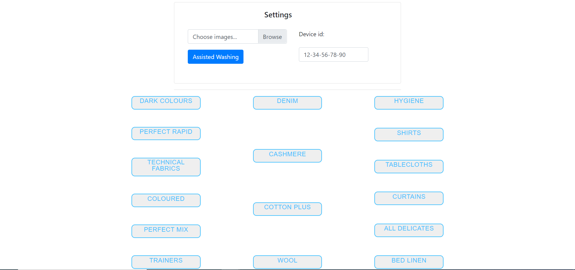
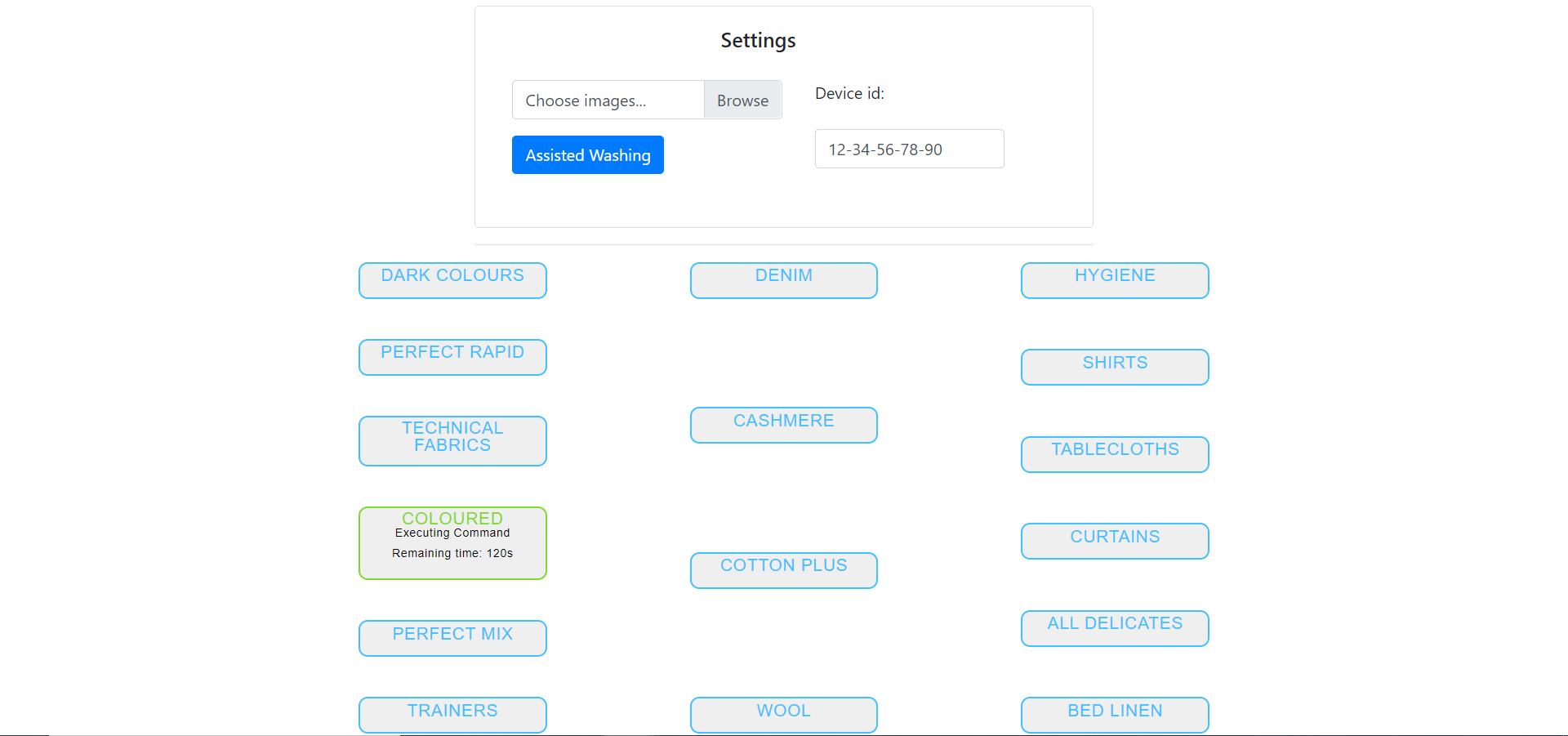
Consolle
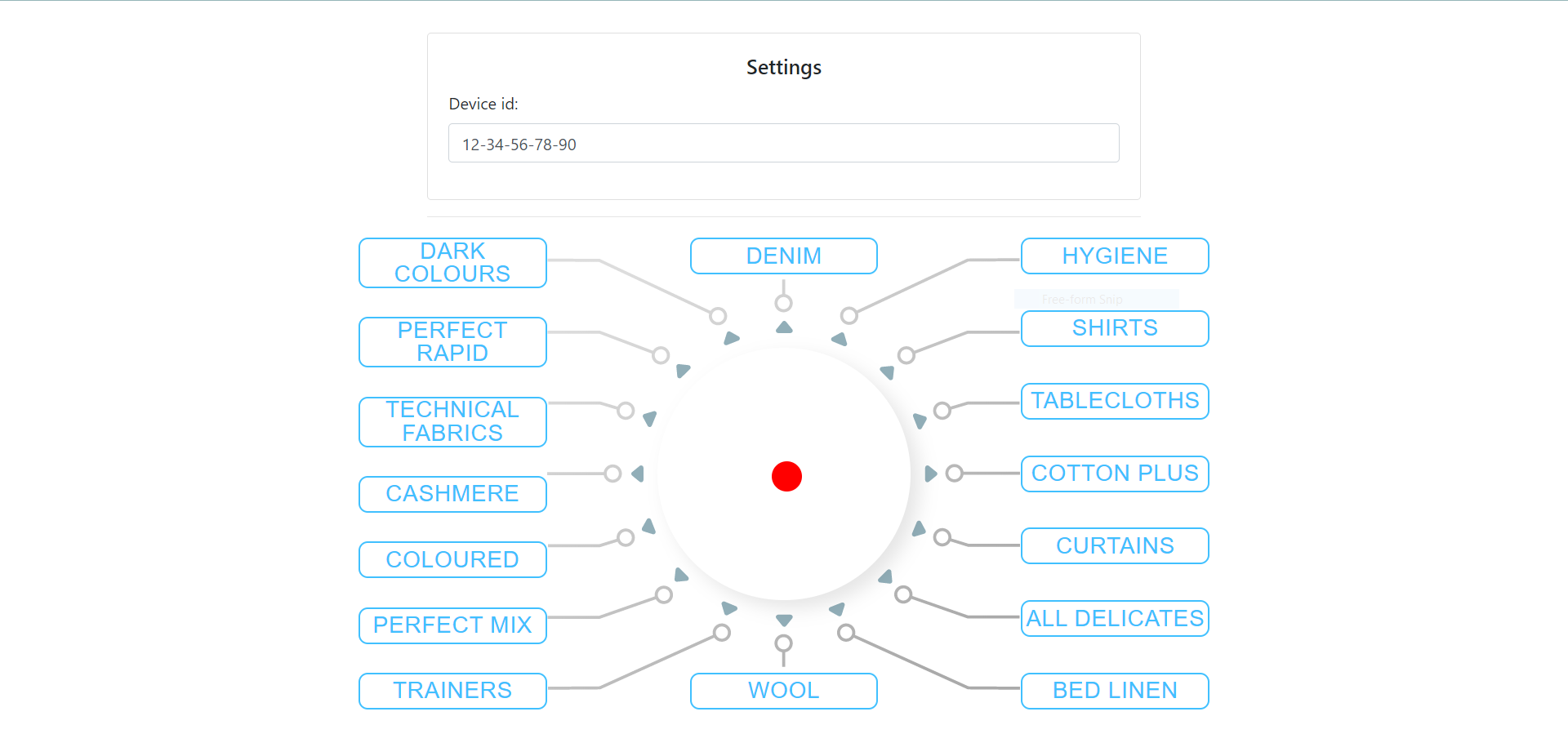
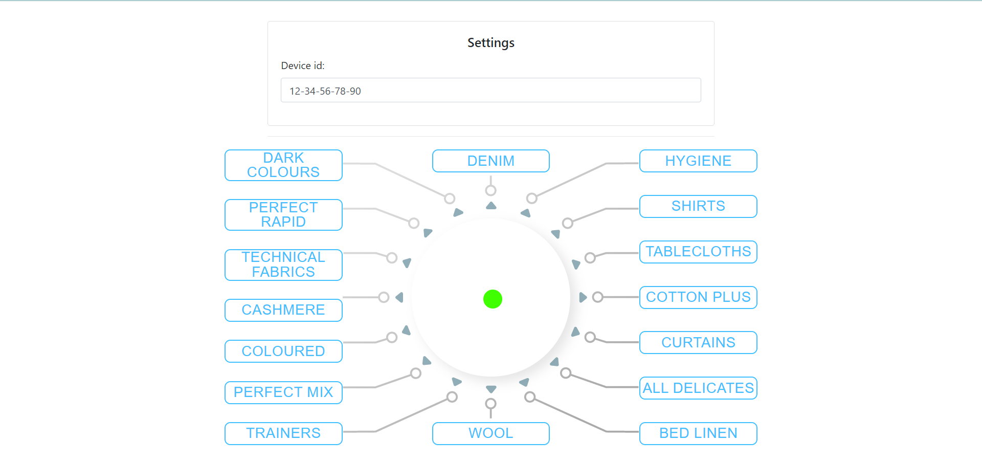
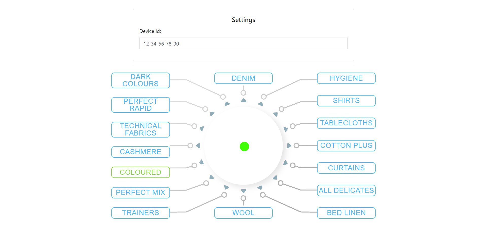
The consolle is the place from where the admin can see the status of the appliance. It should mimic the behaviour of the washing machine control panel.
Here below there are some pictures that show:
- Consolle when the Washing Machine is not connected (red dot).
- Consolle when the Washing Machine got connected (green dot).
- Consolle when the Washing Machine is executing “COLOURED” program.
Mobile App
In this section are displayed the screenshots related to the Mobile App UI.