Home Energy Monitor
Need: get a simple home electricity consumption monitoring system for getting insights into power consumption and utility tariffs.
On the market, this kind of device is not easy to find and often it happens to be really expensive and complicated to install. When I realised this, I decided to use the skills I acquired during my spair time projects and build my own system from scratch.
The main components of the system are:
- A basic acquisition system with simple analog signal processing;
- Arduino Uno for digitalisation and digital filtering of the signal;
- Raspberry Pi 3 for storing the acquired data and for hosting the web-server.
Additionally, also a Simulation Tool in Python for verifying correct output of the various filter.
Before starting with the description of the system, it’s useful to declare the sensors that were chosen for building the system:
The Analog Signal processing circuit was designed starting from considering the information contained in the datasheets (SCT-013-020 and SCT-013-030).
As the topology of the Current Transformer is the same, the analog circuit has the same topology as well.
The main goals of the circuit are:
To achieve the objectives, the circuit is divided in three stages:
- High-Pass Filter and Polarisation;
- Gain/Amplification;
- Low-Pass Filter.
The schematic of the circuit is shown in the image below.
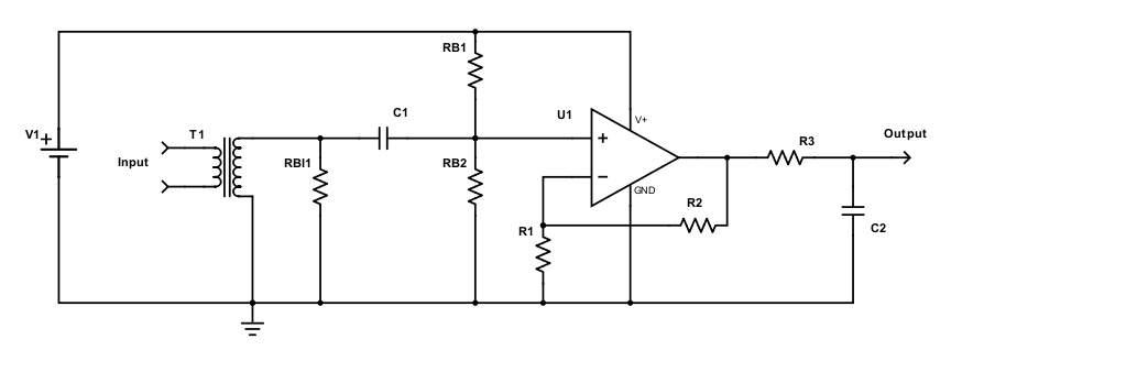
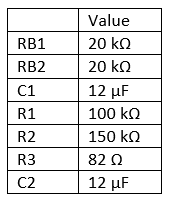
The parameters defined in Figure 2 are resumed in the following table.
The transfer function of the circuit is defined as:
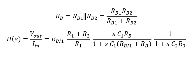
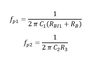
The poles are:
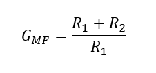
Whereas the gain in the pass-band range is defined approximately as:
The values chosen for the components are:
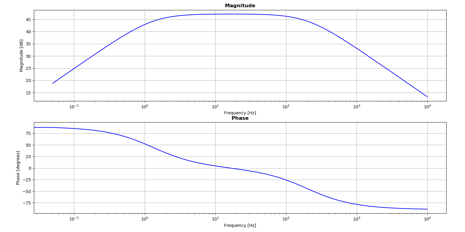
Filter Simulator
For verifying the results, a basic simulation tool was implemented in Python. The obtained transfer function magnitude and phase are plotted in the picture below.
- Acquisition System
The acquisition system was required as no smart current sensors were available off-the-shelf.
The currents to monitor are:
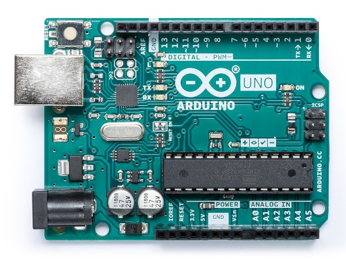
This configuration was suitable for the Arduino Uno Analog Input ports (see figure below).
The Arduino sketch had two main tasks:
- Acquire the analog samples from the various circuits;
- Apply a basic digital filter on the acquired signals;
- Compute the rms of the signal periodically;
- Communicate it to the main board (i.e. Raspberry Pi).
2.1 Digital Filter and Simulation
In this section, it is discussed only the design and simulation of the Digital Filter. The implementation details are discussed later in a dedicated section.
As low frequencies are diminished by the analog filter, but not completely removed, it was required further action. The digital filter consists in this application in a High-Pass Filter with cutting frequency set at 10 Hz. The implementation is based on a moving average with window set to 0.1 seconds.
While acquiring samples, the program will remove low-frequencies and compute the RMS of the resulting signal.
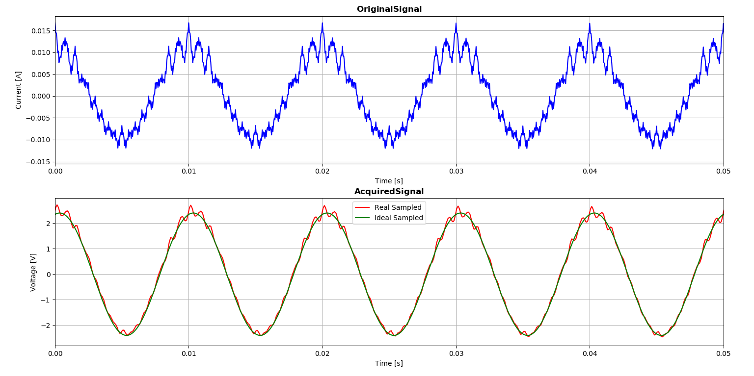
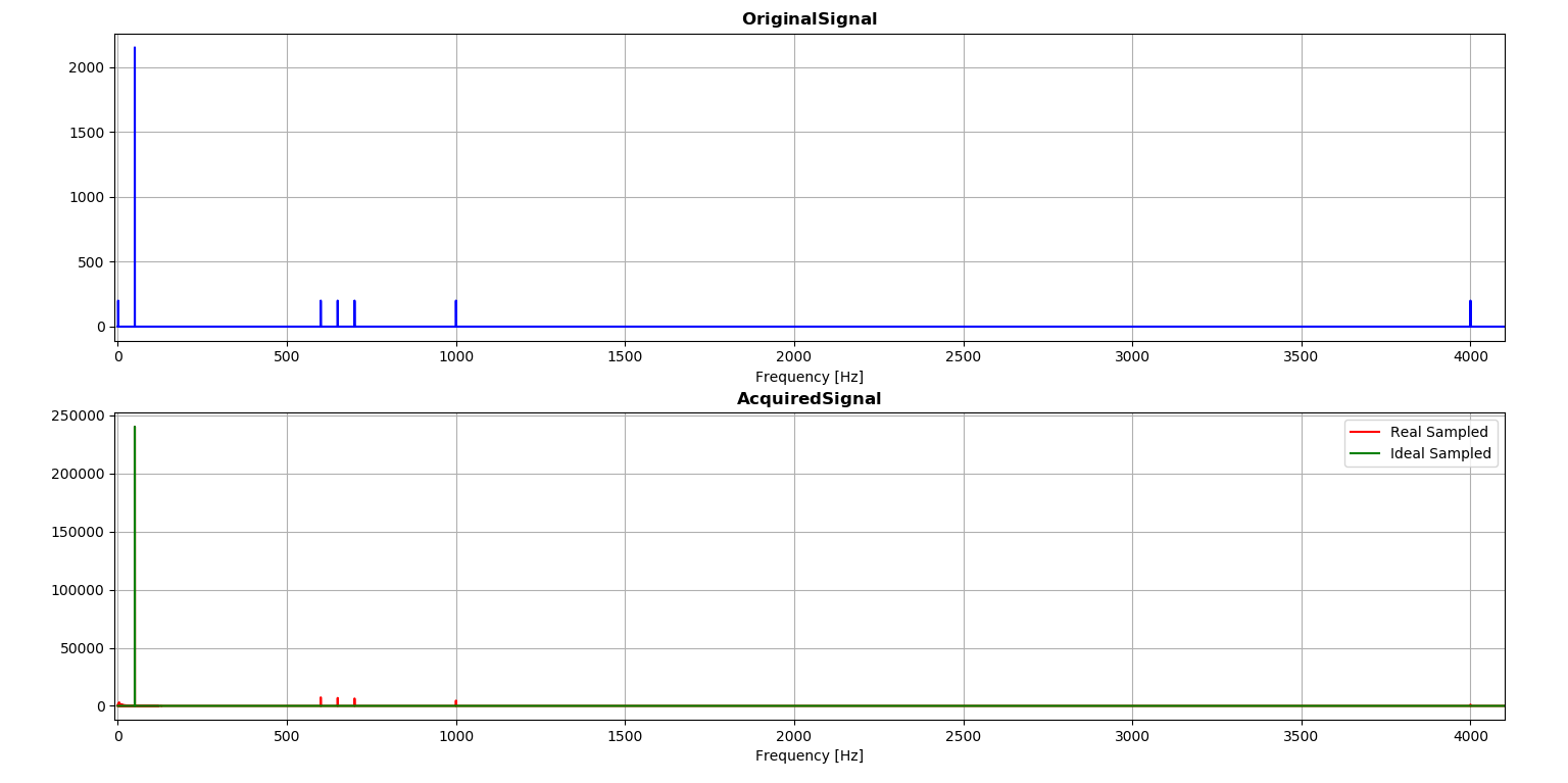
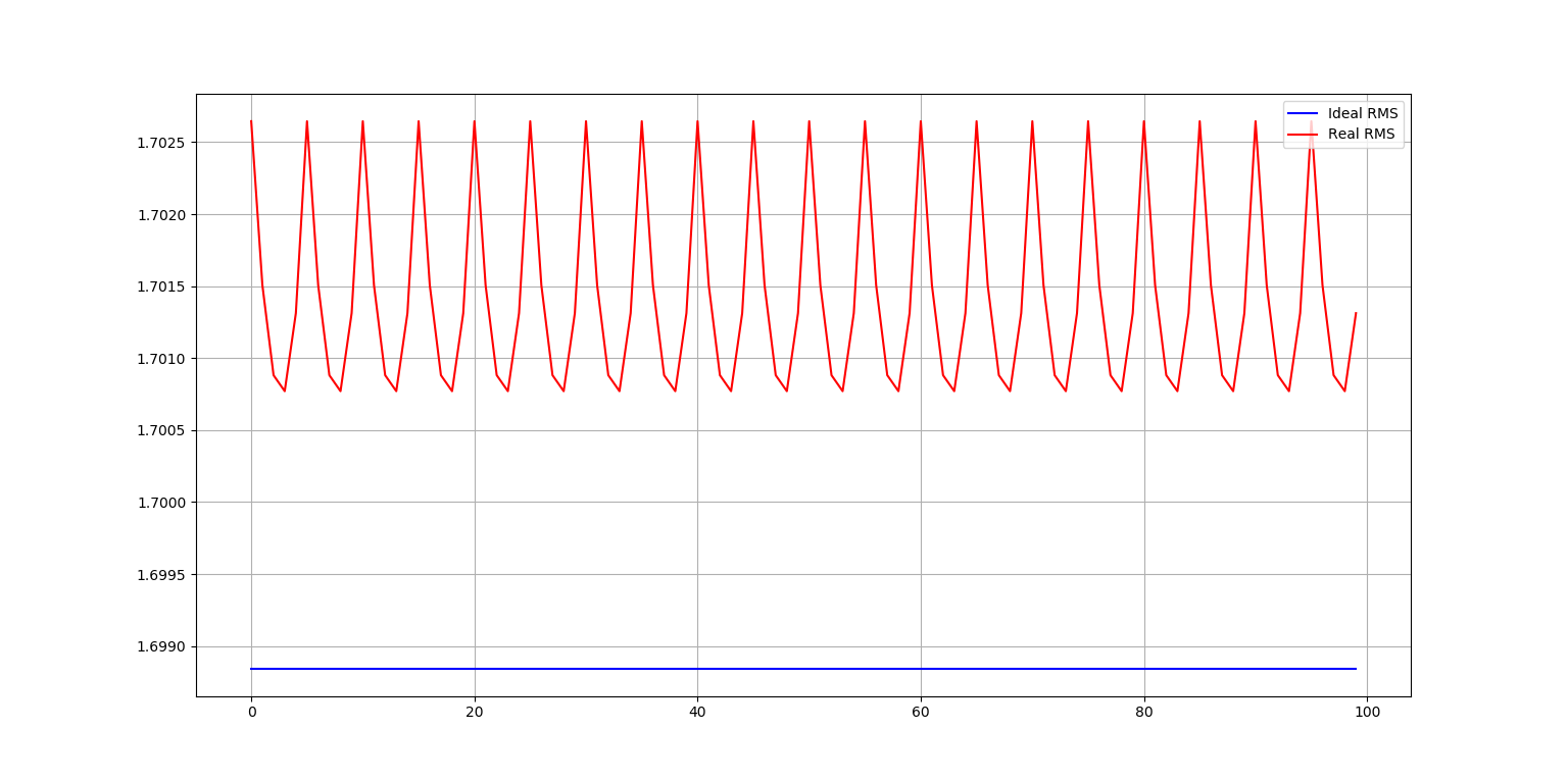
In order to verify that the designed filter fitted the needs, the Python simulator was expanded with a time-domain simulation of all the stages of the filter. In doing so, it was taken into consideration also the sampling accuracy of Arduino Uno ADC (10 bits).
Figures 4 and 5 (below) show the comparisons of the original noisy signal and the
As shown in figure 4 and 5 below, the filter can attain an estimated accuracy of the overall Acquisition System of beyond 99.7% (for the RMS).
The input signal was composed as follows:
2.2 Arduino Code
Arduino board code has two main functions:
- Digitalise the signal;
- Process with simple digital filtering in order to clean from noise.
As Arduino programming language adds excessive overhead in its execution, the choice was to develop the Digital Filtering with a C++ library.
2.3 Overall System
Here below some pictures of the acquisition board.
[Coming soon]
- Server Application
The web-application is hosted on the Raspberry Pi 3 board and it’s based on Django framework.
Django web-app server, which allows to reach via HTTP request to HTML pages that provide access to system functionalities and allow the visualisation of data using graphs.
- Arduino server, which is a Python-based serial server hosted on the Raspberry Pi that allows communication with Arduino board. The server is implemented as a different Django App which has some scheduled tasks for acquiring incoming data.
- Overall System Architecture
Description of Raspberry Pi and system composition.
Arduino Server
Python Django server
Dockerisation and architecture
3.1 Arduino Server
The serial server is hosted on the Raspberry Pi and has the task to manage the connection with the Arduino board. The driver reads the incoming packets, one per second, and averages them by different time periods:
- 1 minute interval;
- 15 minutes interval;
- 1 hour interval;
- 1 day interval.
The packets are stored immediately in the local database. The aggregations are run by some specific scheduled task, which reads the packets in the database and aggregates the values.
Once a day, another scheduled task cleans the packets older than 36 hours, in order to keep the size of the database manageable.
3.2 Python/Django Web-Server
The Django server offers:
3.3 System Architecture
In the section, the overall system architecture is described.
[Coming soon, image of sensors-acquisition board-arduino-rpi]
[coming soon, image of software deployed with Nginx]
Here below some video that shows the working operation of the system.
[Coming soon]