Harmonic Balance Method
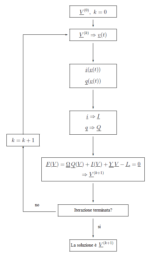
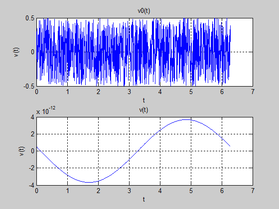
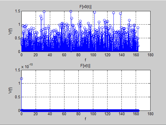
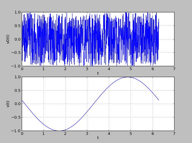
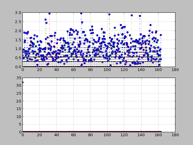
During my Master of Science in Electronic System Engineering I had a course about “Network’s Theory”. The course was about the analysis throught mathematical methods of the electrical networks. I had the opportunity to exchange the final test with the developing of a project. I worked with my classmate and friend Giacomo Petracca over the development of the “Harmonic Balance Method” (HBM). The method is an iterative method that mainly matters about networks in which there are linear and non-linear components in frequency domain. As probably the reader knows, the solution of these systems is not simple and we should pass through the solution of differential equation’ systems. Luckily this is not the only solution. The method we implemented, in fact, works giving a inititial solution and during the iterations filters better the frequencies present in the network, finally ending with the proper solution. We had also to understand and implement Newton for matrices with some tricks in order to speed up the solution of the system.
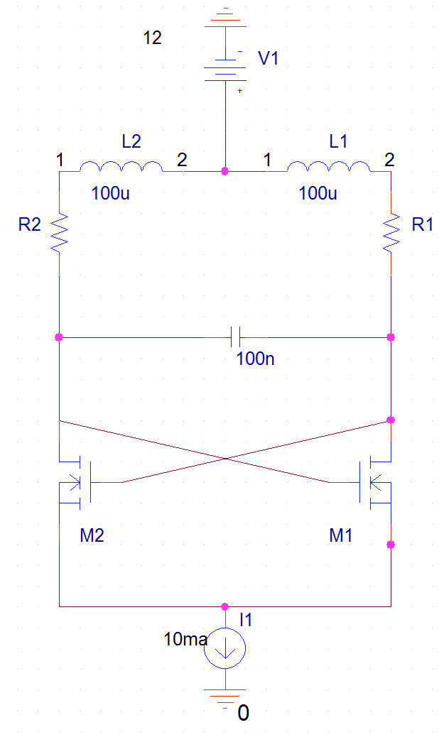
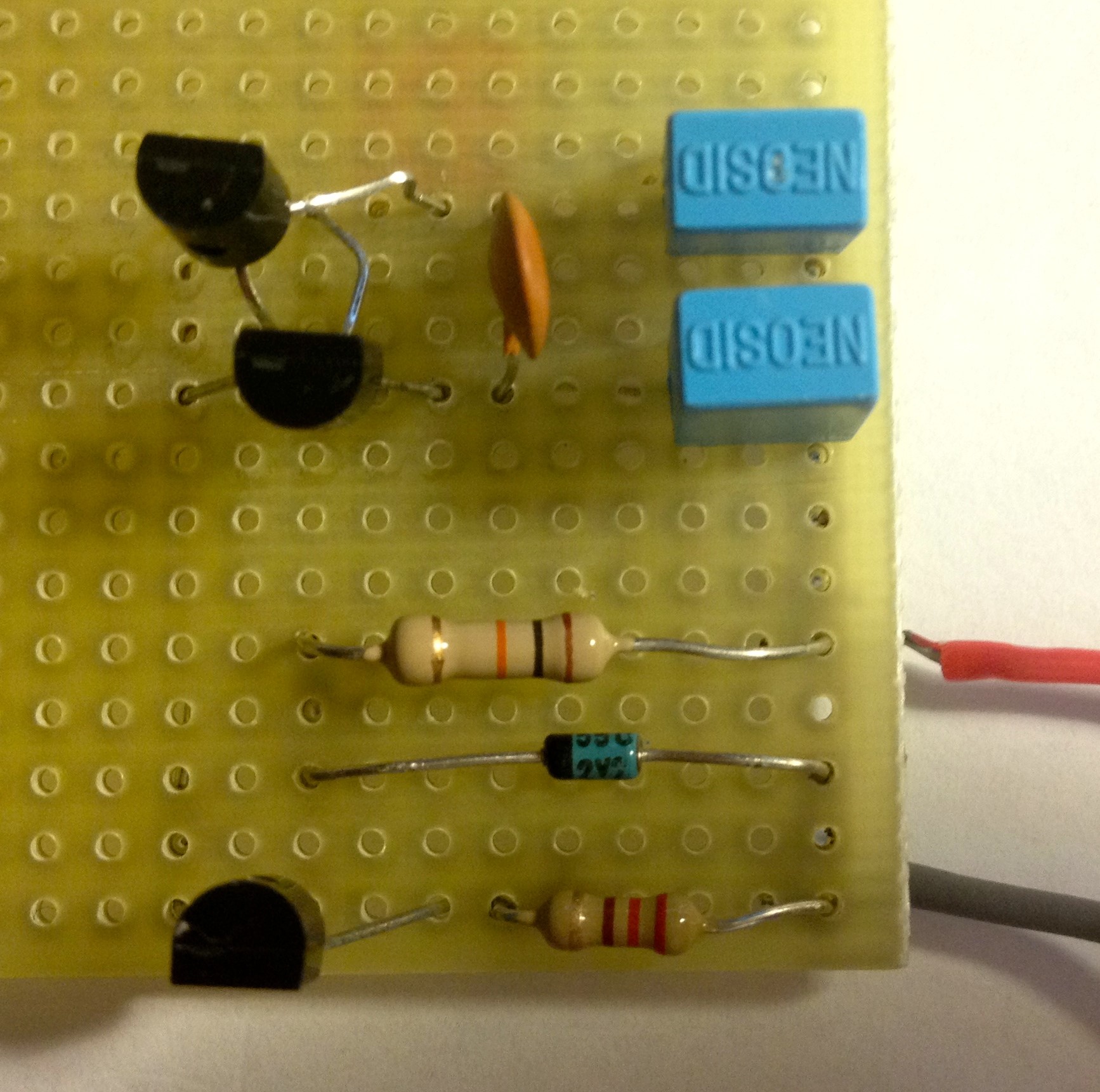
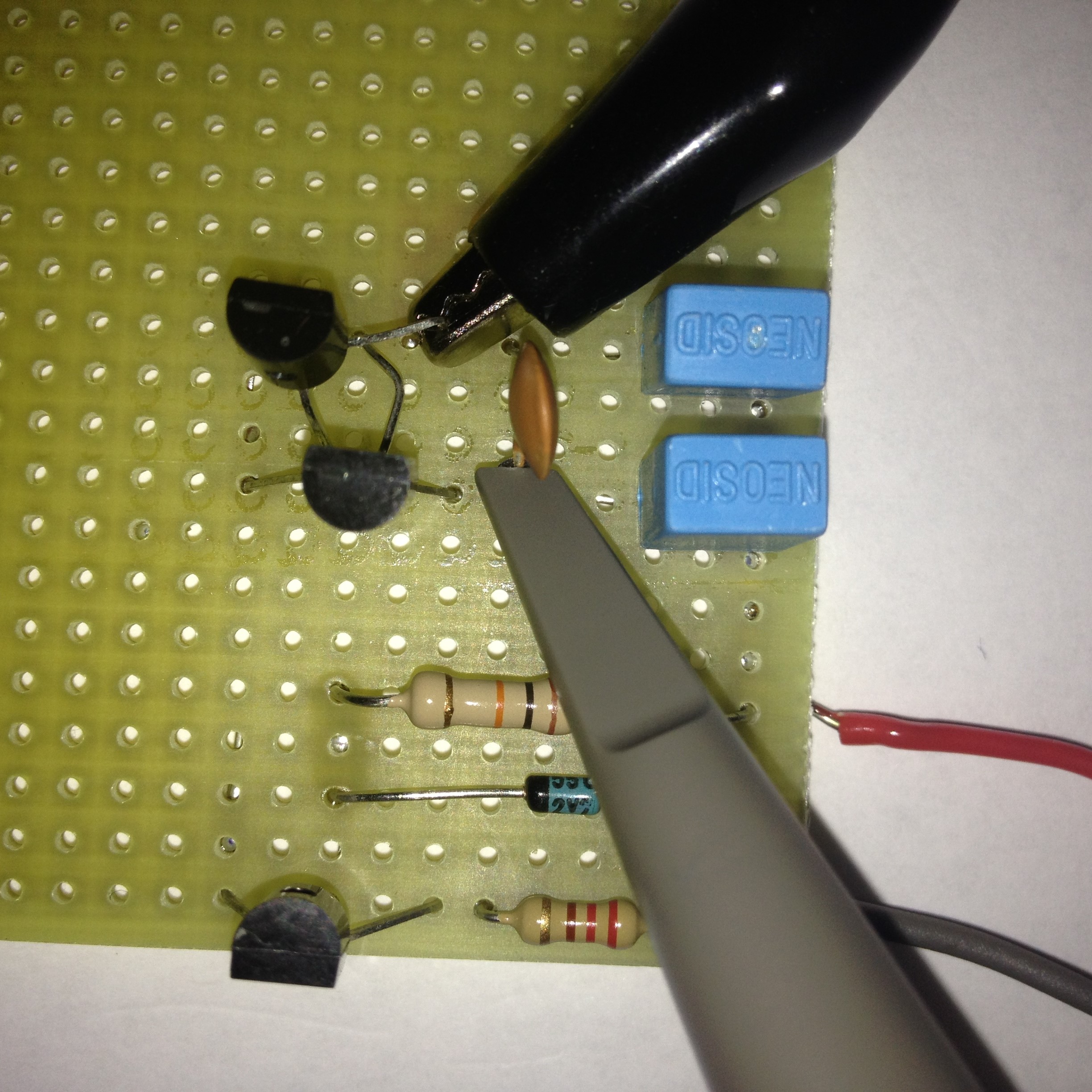
The project was firstly modelled in UML (mainly due to the complexity of the method, HBM and Newton), secondly we realized a Matlab code, then a Python program and finally we implemented the system with a circuit using OrCad and later the welding tools.
The report of the project is downloadable here.
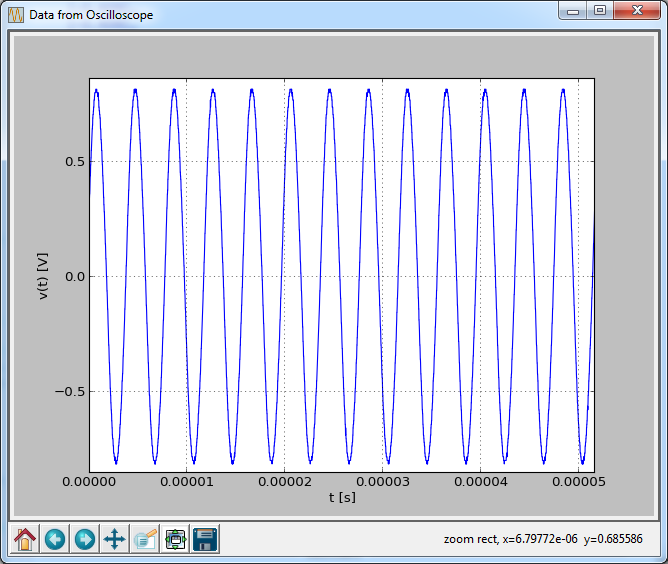
I present here below the pictures that mainly are representative of the project: